Hey, so we all know the Raspberry Pi, right? It’s an awesomely tiny and cheap print board that holds a complete computer on it with a number of interesting connectors and ports. Thanks to a friend of mine in England (thanks Ben!) I was able to get one fairly quickly. So when I got it I just had to find a good purpose for it. Since I handle a lot of hard drives that need to be wiped to ensure sensitive data doesn’t get into the wrong hands, I figured I may as well create a stand-alone hard drive wiping station.
Raspberry Pi + SATA dock = HDD wiper
Yup that’s right, I combined a Raspberry Pi and a SATA dock to create a monster. Basically all it does is power on, wait for a SATA drive to be docked, and then it will write it full of zeroes until it’s full! But it does it with lights and sound effects to indicate when it’s ready to accept a drive and when it’s done wiping one. Of course someone might point out that writing zeroes isn’t the BEST method of ensuring a drive is empty – but I can easily change the code on this box to do any kind of wiping process.
The Raspberry Pi HDD Wiper in action:
[hana-flv-player
video=”/videos/raspberrypihddwiper.mp4″
width=”830″
height=”472″
/]
Reveal your secrets!!
Building it was a fun thing to do, and not that hard. Unexpectedly everything went very smooth. I kind of expected something bad to happen like software not working, or the device not booting straight away – but no, everything worked just fine immediately. The only thing that gave me some trouble was the python package for the GPIO header, but that got sorted easily as it turned out I was using the wrong package and some of the instructions out on the internet were a bit out of date. For those that want it, below is more information on the project and how I got it all to work. Just click the blue links to see pictures/explanation.
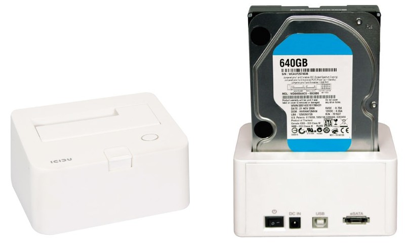
[spoiler show=”I needed a dock with some extra space inside – I went for the Icidu SATA USB2.0/eSATA dock.” hide=”I needed a dock with some extra space inside – I went for the Icidu SATA USB2.0/eSATA dock.”]I took these pictures off the website that I bought it from. Boy, that photographer must have no clue about computers at all because as you can see from the label on the hard drive, the hardware was in the dock the wrong way around – facing backwards. [/spoiler]
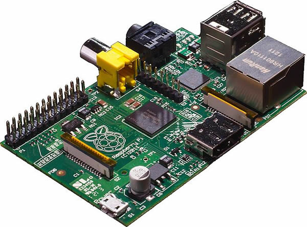
[spoiler show=”Obviously the next step was to get a Raspberry Pi.” hide=”Obviously the next step was to get a Raspberry Pi.”]Obviously the next step was to get a Raspberry Pi. In order to fit it into the case I removed the yellow composite video output header from the print. I didn’t need it and I was using the HDMI port anyways for the initial setup, and SSH through the ethernet port after that. To people that are reading this and are eagerly awaiting their own Raspberry Pi, and to sensitive readers: I’m sorry for the sacrilege.

[/spoiler]
[spoiler show=”I needed to make a choice on operating system – I went for ‘Raspbian’.” hide=”I needed to make a choice on operating system – I went for ‘Raspbian’.”]
I needed to make a choice on operating system – I went for “Raspbian”. It came recommended by the manufacturer of the Raspberry Pi and it is based on Debian, which is an operating system that I am accustomed to. The version I used was based on Debian Wheezy and works quite well with the Raspberry Pi board. I installed it on a 4GB SD card using the image I downloaded off of www.raspbian.org, using their Win32Imager tool. That step is so easy and well documented that I don’t feel I need to document it here. After that step I just stuck the SD card in, plugged a micro-SD power feed into the board and hooked up an HDMI screen and USB keyboard. After a quick test it seemed to be booting okay, so I gave it a fixed IP address, used the built-in tool to grow the partition size to use all of the 4GB on the SD card, and finally set up SSH access so I could just access it through the network port from my main computer using PuTTy. Easy as Pi.[/spoiler]
[spoiler show=”Using GPIO to switch on lights and stuff.” hide=”Using GPIO to switch on lights and stuff.”]
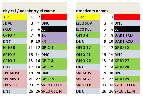
Using GPIO to switch on lights and stuff. This was actually not part of my original goal but I have this thing for blue LED lights and hi-tech stuff so when I saw that GPIO header I just had to do SOMETHING with it. So I ripped open the SATA dock and found some places to put LED lights in and I wired them up to the GPIO pins. I found a file on the internet that I’ve taken a screenshot of here that shows the pin numbers and what they do. Using a Python library called Raspberry GPIO which is available from GoogleCode Projects and the pin numbers on the GPIO header it is possible to create a simple python script that switches an LED on or off. Since the GPIO already has a 3.3v output this makes it VERY easy to hook this up. I just put the ground on the output pins (different one per LED) and the positive on the 3.3v pin (all on the same).
If you look on the Raspberry Pi board there should be a mention of “P1” which should be one of the two pins closest to the corner of the print board. The one closest to the corner is actually pin 2. So one row of the pins is all even, the other row is all odd, like shown in this table here. When you look at the chart below that, keep in mind that the RPi.GPIO column indicates the number to use in the python script using the RPi GPIO library.


Here’s a sample script to switch on and off the LED lights connected to pins 12, 13, 15 and 16. Yeah I know, I don’t understand the logic behind “False” being the “on” state, and “True” being the “off” state, but whatever – it works. [code]
from time import sleep
import RPi.GPIO as GPIO
GPIO.setmode(GPIO.BOARD)
GPIO.setup(12, GPIO.OUT)
GPIO.setup(13, GPIO.OUT)
GPIO.setup(15, GPIO.OUT)
GPIO.setup(16, GPIO.OUT)
GPIO.output(12,False)
GPIO.output(13,False)
GPIO.output(15,False)
GPIO.output(16,False)
sleep(3)
GPIO.output(12,True)
GPIO.output(13,True)
GPIO.output(15,True)
GPIO.output(16,True)
sleep(3)
[/code] [/spoiler]
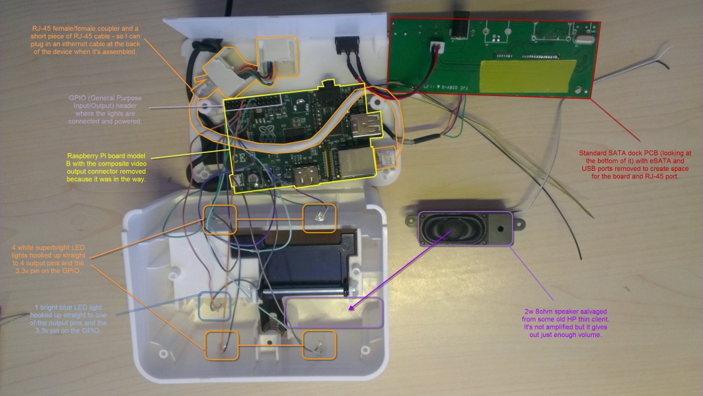
[spoiler show=”HDD wiper dissected. Large picture with explanations on where the parts are and what they do.” hide=”HDD wiper dissected. Large picture with explanations on where the parts are and what they do.”]HDD wiper dissected. Large picture with explanations on where the parts are and what they do. Click on the picture for an enlargement. The construction was done fairly simply using a glue gun and a soldering iron and some small sanding and filing tools to make space here and there for the Raspberry Pi board to fit in. As you can see I had to put it in somewhat crooked, but it’s fine. The PCB on the right is now seen from the bottom – it flips up over the RJ-45 port outlined in orange and hangs a little over the Raspberry Pi board outlined in yellow. The top casing flips over too and fits on the base. There’s only a few millimeters of space here and there, it’s a pretty tight fit. The USB connection is done by soldering directly onto the connection points on both PCBs as the USB plugs themselves are too big to fit in the case. Same goes for the audio wiring – see the black wire and the two yellow wires coming out to the right? This pictures was taken just before I finished soldering those up to the black and white wires of the speaker (see wires at top right of picture).

[/spoiler] [spoiler show=”Sound effects using mpg321 command line audio player.” hide=”Sound effects using mpg321 command line audio player.”]Sound effects using mpg321 command line audio player. As it turns out all you really need to pull this off on Raspbian Wheezy is to just install two packages that enable audio and audio playback on the Raspberry Pi. Once the packages are installed using the code below you can just make sound by having an MP3 file handy and typing “mpg321 playme.mp3” and voila, off it goes. So I grabbed some audio files from Windows 7 (hardware disconnect/hardware connect) sounds and I made a little sound file on my keyboard and voila.
sudo apt-get install alsa-utils
sudo apt-get install mpg321[/spoiler]
[spoiler show=”Monitoring the syslog for events to see if a hard drive is connected or not.” hide=”Monitoring the syslog for events to see if a hard drive is connected or not.”]Monitoring the syslog for events to see if a hard drive is connected or not. That’s the method I used to do this. I probably am breaking some holy rules of conduct with the hack I made to do this, and to be honest I’m kind of embarrassed at how dirty my code is (which is why I haven’t posted it here). What I did was quite simply echo “” > /var/log/syslog and after that just monitor it using cat and grep for a specific key string – I believe it was “logical blocks” – that only shows up when a hard drive is plugged into the USB dock. That’s my trigger for detecting a hard disk and it seems to work fine. After it finds it, it wipes syslog again and the code continues to monitor for a ‘disconnect’ event. Insert some light effects and sound effects and voila, project complete.[/spoiler]

0 Comments